ASDShellQ4#
This command is used to construct an ASDShellQ4 shell element.
- element ASDShellQ4 $tag $n1 $n2 $n3 $n4 $secTag <-corotational> <-noeas> <-drillingStab $drillingStab> <-drillingNL> <-damp $dampTag> <-local $x1 $x2 $x3>
Argument |
Type |
Description |
|---|---|---|
$tag |
integer |
unique integer tag identifying element object |
$n1 $n2 $n3 $n4 |
4 integer |
the four nodes defining the element (-ndm 3 -ndf 6) |
$secTag |
integer |
unique integer tag associated with previously-defined SectionForceDeformation object |
-corotational |
string |
optional flag, if provided, the element uses non-linear kinematics, suitable for large displacement/rotation problems |
-noeas |
string |
optional flag, if provided, the membrane behavior will not be enhanced with the AGQ6-I enhanced assumed strain formulation. |
-drillingStab $drillingStab |
string + float |
optional flag, if provided, the user can specify the stabilization parameter $drillingStab to stabilize the 1-point quadrature drilling DOF formulation (default = 0.01). |
-drillingNL |
string |
optional flag, if provided, the Hughes-Brezzi drilling DOF formulation considers the non-linear behavior of the section. |
-damp $dampTag |
string + integer |
optional, to activate elemental damping as per elementalDamping |
-local $x1 $x2 $x3 |
string + 3 float |
optional, if provided it will be used as the local-x axis of the element (otherwise the default local X will be the direction of the 1-2 side). Note: it will be automatically normalized and projected onto the element plane. It must not be zero or parallel to the shell’s normal vector. |
The ASDShellQ4 element is a 4-node general purpose thick shell element with the following features: #. The membrane behavior is enhanced with the AGQ6-I [ChenEtAl2004] formulation, which makes the element almost insensitive to geometry distortion, as opposed to standard iso-parametric elements. #. The drilling DOF is treated with the Hughes-Brezzi [HughesEtAl1989] formulation, with special care to avoid membrane locking, using a 1 point quadrature plus stabilization. This formulation constrains the drilling DOFs to the rigid body rotation via a penalty parameter as a function of the initial in-plane shear modulus. However, when using strain-softening materials, this (elastic) constraint may overstiffen the element as the in-plane shear modulus degrades. As a remedy in such a situation, the user can choose to make this constraint non-linear. #. The plate bending part is treated using the MITC4 [DvorkinEtAl1984] [BatheEtAl1985] formulation, to avoid the well known transverse shear locking behavior of thick plate elements. #. It can be used to model both flat and warped geometries. #. Kinematics can be either linear or corotational. The corotational kinematics is based on the work of Felippa et al., i.e. the EICR [Felippa2000] [FelippaEtAl2005] (Element Independent Corotational formulation). Finite rotations are treated with Quaternions. #. It uses a full 2x2 Gauss quadrature, so it has a total of 4 integration points.
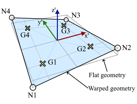
Fig. 31 Nodes, Gauss points, local coordinate system, warped and flat geometry#
Valid eleResponse queries to the ASDShellQ4 element are:
"force","forces","globalForce", or"globalForces":
Internal forces at the element’s nodes.
Orientation: global coordinate system.
Size: 24 columns of data, 6 components for each one of the 4 nodes.
"material $secTag $secArg1 ... $secArgN":
Section response at section $secTag
$secTag is the 1-based index of the integration point (1 to 4).
‘$secArg1 … $secArgN’ are the arguments required by the SectionDeformationObject at the requested integration point.
Examples#
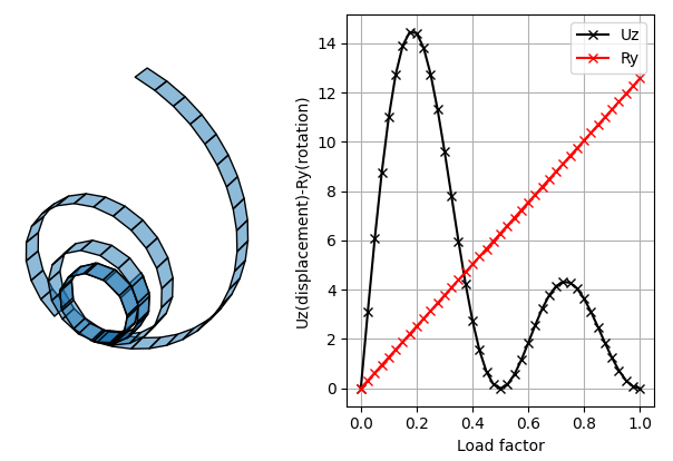
Example 1 - Cantilever Bending Roll-up (corotational)#
A Cantilever beam is subjected to a total end-moment about the Y axis \(M_y = n 2 \pi EI/L\), where \(n\) is the number of rotations (2 in this example). The files for this example can be downloaded from https://gallery.stairlab.io/examples/shellcircle/
Example 2#
# set up a 3D-6DOFs model
model Basic -ndm 3 -ndf 6
node 1  0.0  0.0 0.0
node 2  1.0  0.0 0.0
node 3  1.0  1.0 0.0
node 4  0.0  1.0 0.0

# create a fiber shell section with 4 layers of material 1
# each layer has a thickness = 0.025
nDMaterial ElasticIsotropic  1  1000.0  0.2
section LayeredShell  11  4   1 0.025   1 0.025   1 0.025   1 0.025

# create the shell element using the small displacements/rotations assumption
element ASDShellQ4  1  1 2 3 4  11
# or you can use the corotational flag for large displacements/rotations (geometric nonlinearity)
element ASDShellQ4  1  1 2 3 4  11 -corotational

# record global forces at element nodes (24 columns, 6 for each node)
recorder Element  -xml  force_out.xml  -ele  1  force
# record local section forces at gauss point 1 (8 columns: | 3 membrane | 3 bending | 2 transverse shear |)
# note: gauss point index is 1-based
recorder Element  -xml  force_gp1_out.xml  -ele  1  material  1  force
# record local stresses at fiber 1 of gauss point 1 (5 columns: Szz is neglected (0) )
# note: fiber index is 1-based (while in beams it is 0-based!)
recorder Element  -xml  stress_gp1_fib0_out.xml  -ele  1  material  1  fiber 1 stress
# set up a 3D-6DOFs model
model = ops.Model(ndm=3, ndf=6)
model.node(1, (0.0, 0.0, 0.0))
model.node(2, (1.0, 0.0, 0.0))
model.node(3, (1.0, 1.0, 0.0))
model.node(4, (0.0, 1.0, 0.0))

# create a fiber shell section with 4 layers of material 1
# each layer has a thickness = 0.025
model.material('ElasticIsotropic', 1, 1000.0, 0.2)
model.section('LayeredShell', 11, 4, (1,0.025),  (1,0.025),  (1,0.025),  (1,0.025))

# create the shell element using the small displacements/rotations assumption
model.element('ASDShellQ4', 1, (1,2,3,4), 11)
# or you can use the corotational flag for large displacements/rotations (geometric nonlinearity)
# model.element('ASDShellQ4', 1, (1,2,3,4), 11, corotational=True)

# record global forces at element nodes (24 columns, 6 for each node)
model.recorder('Element', "force", xml='force_out.xml', ele=1)
# record local section forces at gauss point 1 (8 columns: | 3 membrane | 3 bending | 2 transverse shear |)
# note: gauss point index is 1-based
model.recorder('Element', '-xml', 'force_gp1_out.xml', '-ele', 1, 'material', '1', 'force')
# record local stresses at fiber 1 of gauss point 1 (5 columns: Szz is neglected (0) )
# note: fiber index is 1-based (while in beams it is 0-based!)
model.recorder('Element', '-xml', 'stress_gp1_fib0_out.xml', '-ele', 1, 'material', '1', 'fiber', '1', 'stress')
Code Developed by: Massimo Petracca at ASDEA Software, Italy.
Chen, Xiao-Ming, et al. “Membrane elements insensitive to distortion using the quadrilateral area coordinate method.” Computers & Structures 82.1 (2004): 35-54. (Link to article)
Hughes, Thomas JR, and F. Brezzi. “On drilling degrees of freedom.” Computer methods in applied mechanics and engineering 72.1 (1989): 105-121. (Link to article)
Dvorkin, Eduardo N., and Klaus-Jurgen Bathe. “A continuum mechanics based four-node shell element for general non-linear analysis.” Engineering computations (1984). (Link to article)
Bathe, Klaus-Jurgen, and Eduardo N. Dvorkin. “A four-node plate bending element based on Mindlin/Reissner plate theory and a mixed interpolation.” International Journal for Numerical Methods in Engineering 21.2 (1985): 367-383. (Link to article)
Felippa, Carlos A. “A systematic approach to the element-independent corotational dynamics of finite elements”. Technical Report CU-CAS-00-03, Center for Aerospace Structures, 2000. (Link to article)
Felippa, Carlos A., and Bjorn Haugen. “A unified formulation of small-strain corotational finite elements: I. Theory.” Computer Methods in Applied Mechanics and Engineering 194.21-24 (2005): 2285-2335. (Link to article)